BOG modelling with Eznec 5 and AutoEZ
Yes, this is a resonant antenna, nothing to do with Beverages!
I tried to model my BOG with AutoEz starting from the standard “Beverage with 0.25 radials” model found in the EZNEC library. I changed the units to metrical, the ground type to my very poor, almost desert situation, and applied the AutoEz variables.
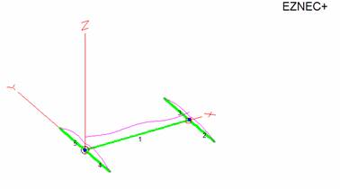
Down here is the antenna image with the 0.25 radials.
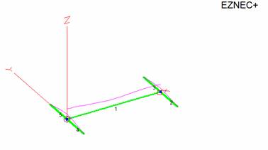
And this is the same image with the shorted radials, showing the correct current distribution as recommended by the program authors (read below)
At first I tried to find the best F/B varying the length of the BOG wire
Freq. 1.825 – Height: 3 cm. – Ground Real = Sandy (0.002, 10) – Load 250 ohms
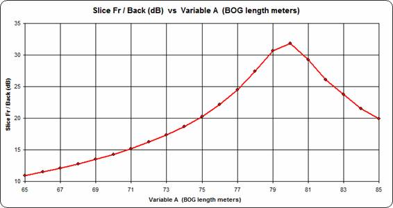
Immediately it was clear that the BOG is a sharp resonant antenna, but it appeared to be too long than expected, what’s wrong in the model?
Both the authors of Eznec and AutoEz answered to help me. Dan McGuire, AC6LA:
“……. I believe the intent of the "0.25 radials" is to simulate a low-impedance connection to ground. This is explained in the EZNEC Help, topic "Connecting to High Accuracy Ground". As the Help states:
"If a low impedance connection is required, make the radials about a quarter wavelength or odd multiples long, and avoid lengths approaching a half wavelength or multiples. These aren't free space wavelengths, however, but wavelengths for a wire at the radial height. A half wavelength for a wire very close to the ground will be less than in free space, though. You can determine the wavelength by modeling a dipole at the height of the radials and adjusting its length until it's resonant."
From looking at the current on the radials as shown in the first graphic of your document it appears that the radials of your model are a bit too long. For 1.825 MHz at 0.03m above sandy ground I get a resonant dipole length of 56.5m which translates to a "radial" length of 28.25m, much less than WL.25 which is 41.07m.”
And Roy Lewallen, W7EL himself wrote:
“Luis,
You can see by the current distribution on the radial wires that they are electrically longer than a quarter wavelength. At a quarter wavelength, the current should just reach maximum at the junction. I think you'll
find the best efficiency to occur when the radials are an electrical quarter wavelength or shorter, and increasingly poor as they get longer than a quarter electrical wavelength.
The electrical lengthening of the radials is due to the low propagation constant of the ground. The amount of lengthening (the effective velocity factor) that happens depends strongly on the height above ground as well as the ground characteristics. Calculation of the physical length needed isn't simple -- I recommend just shortening them until the current maximum occurs at the junction.
73, Roy, W7EL”
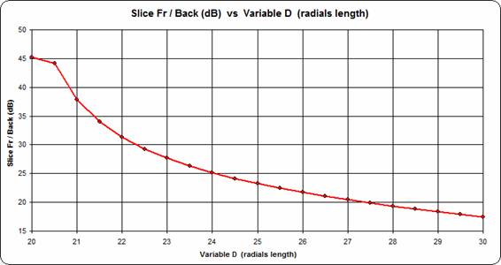
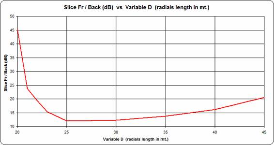
Thus in AutoEz I put the radials length as a variable from 20 to 30 meters , 3 cm. high, for a BOG length of 65 meters and a load of 250 ohms
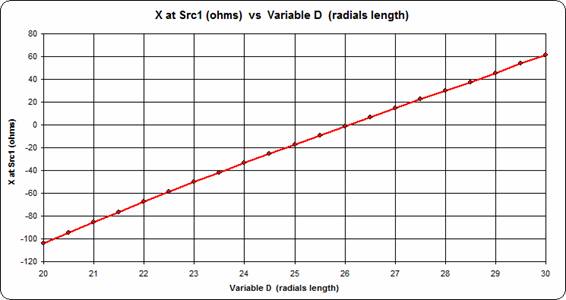
The antenna is resonating on 1.825 MHz (X = 0) with radials length of 26 m. But what’s about the Front to Back, which is our target in the antenna design? As Bruce, K1FZ, said:
“The best BOG antenna pattern to hear DX comes with maximum front to back. This is the reason we try to find the length that gives best F/B.”
Quite simple to select another of the several options in the “Custom” sheet of AutoEZ to get the following graph, which indicates that’s much better to go towards a shorter length.
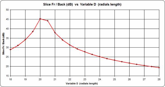
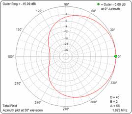
So moved the sweep a bit down and this is the F/B of a BOG 63 meters long, 3 cm. high, with a 250 ohms load and two sets of radials. An impressive F/B of 45 dB is peaking at a radial length of 20 meters.
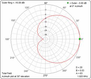
The azimuth plot shows a nice lobe with a good gain (-16 dB) requiring only a modest preamplifier.
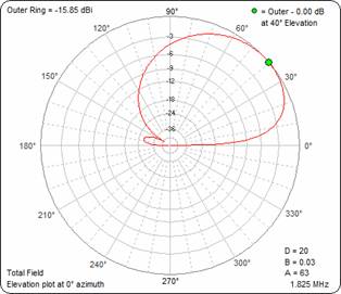
And the elevation one is mainly at high angles as needed at my present low latitude location
Now with the same BOG length of 63 m. let’s make a frequency sweep:
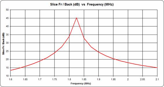
It confirms that the BOG is a sharp resonating antenna which has nothing to do with the classic Beverage and the other broadband receiving loops
But of course this is a model and for sure nobody will get a 45 dB of F/B in the realty!
Now let’s see what happens by varying the load:
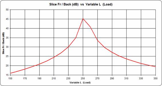
Nothing: given the above parameters and dimensions, the load is perfect with 250 ohms.
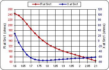
At last, with the same sweep parameters let’s check Resistance and Reactance at the source:
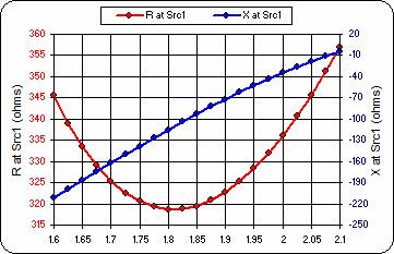
As seen before, when the radials length was chosen, the antenna is resonating higher, around 2.1 MHz, and thus on 1.825 MHz it has at the source a capacitive reactance around 100 ohms with a resistance of 318 ohms. If it were a TX antenna we could use an L-Network, but with receiving antennas a precise match is not required and thus a simple binocular transformer would do the trick.
Modeling with feed system for the Reversible BOG
I inserted the transformer to simulate the feed impedance in the FORWARD position with these relations: Z of the antenna = 250 ohms, Z coax = 75 ohms
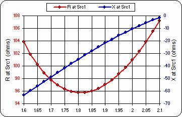
On 1.825 MHz we got R= 96 ohms, Z = -j31 ohms with an SWR of 1.55 on 75 ohms system, not bad for a receiving antenna.
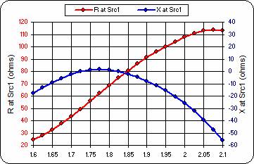
Next I tried to simulate what happens in the REVERSE direction. I moved the load at the beginning of the BOG wire and inserted a 150 ohms transmission line with its VF of 0.73. Changed the transformer to the new relations of 150/75 ohms and got these results:

The pattern is exactly as before, just correctly reversed, but the source impedance worsens to 121 – j73 ohms at 1.825 MHz with an SWR of 2.4, not very well.
Probably the Rev.BOG circuit and transformers calculation do not take into consideration the VF of the line in the “transmission line” mode. With the insertion of an L-Network we could achieve a perfect match, but that’s going to be a complication too difficult to manage for such a simple efficient antenna.
Anyway, just for a funny exercise, let’s use one of the beautiful weapons of AutoEZ.
In the “Objects page” hit on the “Create Impedance Matching Network” button and automatically an L-Network is added, without the need to go on a separate TL program. In my case a series 1.095 pF capacitor with a shunt 8 uH
inductor would give the following perfect match, but not necessary for a receiving antenna.
Raising the BOG at the typical Beverage height
When Gary, KD9SV and Bruce, K1FZ, introduced me to seriously consider a BOG in my difficult situation, I had already tried it without any success: it was simply too long! I thought “longer is better”, but the BOG does not behave like a Beverage.
K1FZ said:
A BOG has too much capacity to ground over its entire length to behave like a traveling wave above ground Beverage does. A BOG becomes a tuned circuit.
As a countercheck I went again on AutoEZ varying the height of the 63 m. BOG from 3 cm. gradually to 0.5 meters and then up to the classic 2.5 m. of a Beverage
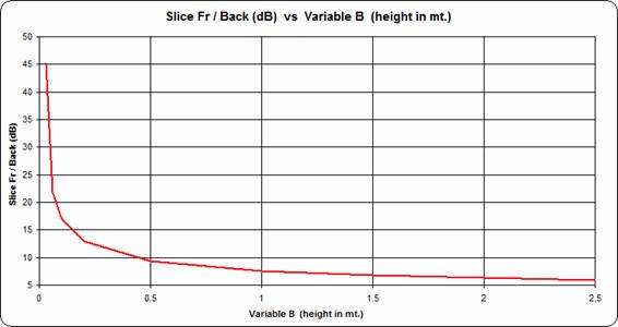
The Front to Back drops from 45 dB to less than 10 dB.
OK, if we raise the BOG we should also lengthen accordingly the radials
With longer radials the F/B rises again at 2 m. height, but still far from the 3 cm high.
In the following graph the wire length is varied from 60 to 75 m., 2 meters high.
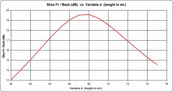
The best F/B occurs with a length of 68 meters, but the curve is much broader: only 6 dB of difference from max to min.
Here is the azimuth pattern for this short Beverage (it is NOT a BOG) 68 m. long, 2 meters high with two 40 m. radials at right angles at each end:
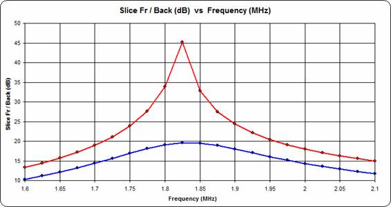
This is the frequency sweep showing the Front to Back of both antennas:
- Red line is the BOG 63 m. long and 3 cm. above ground with 20 m. radials
- Blue line is the Beverage 68 m. long and 2 m. above ground with 40 m. radials
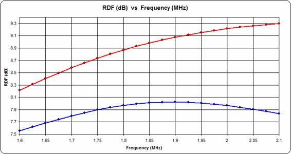
And finally here is the frequency sweep showing the RDF of the same antennas:
- Red line is the BOG 63 m. long and 3 cm. above ground with 20 m. radials
- Blue line is the Beverage 68 m. long and 2 m. above ground with 40 m. radials
This is just modeling with NEC2 and not NEC4 engine, so the results must be taken with caution, but at least the general trend, showing a tuned antenna, should be correct.
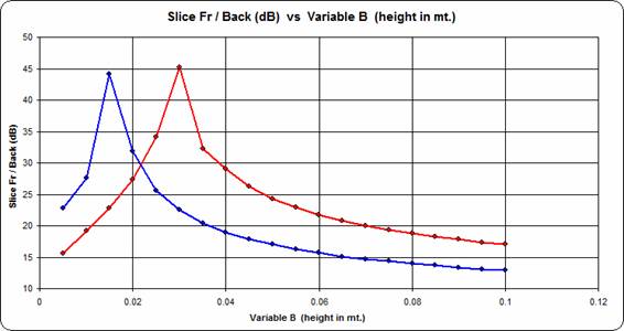
We know that NEC2 engine does not handle wires on ground or very close to ground, so I performed a last test to see which the minimum height for two different grounds is.
In the following graph the red line is for my very poor sandy ground (0.002, 10) showing the peak at 3 cm high, and the blue line is for very good ground (0.0303, 20) showing the peak at a lower height of 15 mm.
This is the conclusive comment received by EZNEC’s Author on my work, many thanks Roy !
Hello Luis,
Yes, you understood and applied what Dan and I said.
Even slightly elevated radials will behave differently than buried ones,
but in most cases (this one included), the difference will be a small
one in efficiency and perhaps a moderate impedance change. With a
sharply tuned antenna like this, you can't expect the resonant frequency
to be exactly like EZNEC predicts, but after you adjust the antenna,
it'll behave very much like EZNEC shows. But even NEC-4 makes the
assumption that the ground is homogeneous to an infinite depth -- which
real ground isn't -- so it's not terribly accurate whenever ground
effects are important. And the only difference between NEC-2 and NEC-4
in this application is in the modeling of the radials. Otherwise the
results will be the same.
73,
Roy, W7EL
Quito, June 19 2015 Luis IV3PRK / HC1PF