The Horizontal Loop at HC1PF
A waste of time ?
The outstanding performance of my Inverted L antenna with a “long” horizontal wire, radiating for sure at high angles, confirmed that the dominant polarization – in this particular location, at 2.400 m. elevation on the equator - is horizontal, rather than vertical as usually happens at middle and high latitudes.
I am always and everywhere heard better than I hear the stations calling me, so I’m aware I must equalize my situation, trying to get down the signals from the ionosphere with the same angle I am sending in.
The easiest solutions should be to receive on the same TX antenna, but the noise level is prohibitive, so I decided to try an horizontal loop.
With AutoEz , the beautiful program by Dan McGuire AC6LA, I performed some modeling and found these results for a square loop of 9 meters side and 6 m. height:
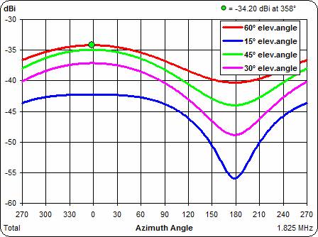
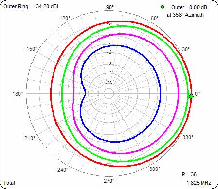
Most of the radiation is at 60 degrees with low directivity, while at lower angles there is some moderate front to back.
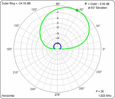
The elevation plot shows max radiation at 63° with the horizontal (green) and vertical (bleu) components.
The source data indicate that a load resistor of 1.050 ohms is needed to get an easy resistive match without reactance.
Freq. Load R at Src. X at Src.
|
1.825 |
500 |
|
|
|
734.52 |
583.72 |
23.994 |
-34.95 |
56 |
|
2.87 |
|
1.825 |
600 |
|
|
|
831.65 |
480.52 |
22.201 |
-34.96 |
57 |
|
2.58 |
|
1.825 |
700 |
|
|
|
909.84 |
372.38 |
21.253 |
-34.90 |
58 |
|
2.31 |
|
1.825 |
800 |
|
|
|
970.39 |
263.15 |
20.839 |
-34.79 |
59 |
|
2.07 |
|
1.825 |
900 |
|
|
|
1014.97 |
155.58 |
20.778 |
-34.66 |
60 |
|
1.86 |
|
1.825 |
1000 |
|
|
|
1045.86 |
51.95 |
20.969 |
-34.52 |
61 |
|
1.67 |
|
1.825 |
1050 |
|
|
|
1056.77 |
2.06 |
21.136 |
-34.44 |
62 |
|
1.59 |
|
1.825 |
1100 |
|
|
|
1065.02 |
-46.40 |
21.341 |
-34.36 |
62 |
|
1.51 |
|
1.825 |
1200 |
|
|
|
1074.47 |
-138.67 |
21.848 |
-34.20 |
63 |
|
1.37 |
|
1.825 |
1300 |
|
|
|
1076.13 |
-224.45 |
22.461 |
-34.04 |
64 |
|
1.24 |
|
1.825 |
1400 |
|
|
|
1071.51 |
-303.64 |
23.155 |
-33.87 |
64 |
|
1.14 |
|
1.825 |
1500 |
|
|
|
1062.01 |
-376.40 |
23.914 |
-33.71 |
65 |
|
1.04 |
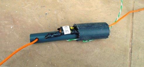
Thus my choice was to use a Cat5 twisted pair, which is balanced and very light, from the loop to the coax cable, and to use two binocular BN73-202 transformers:
The first one with 9/3 turns (7/2 is also ok) to go to 100 ohms and the second one with 4 and 3 turns to go to the 50 ohms coax line.
This is the resulting impedance plot with the AEA CIA antenna analyzer
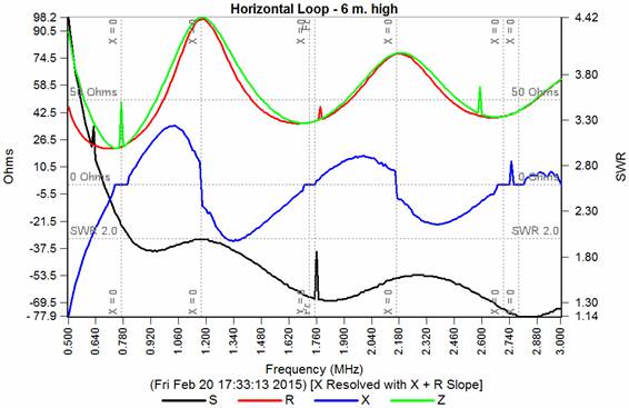
And this is the loop installed on the 6 m. fiberglass poles which were used for the pennants, but the results “on the air” are quite disappointing: the noise is lower, but also ALL the signals are 10 to 20 dB LOWER than on the flag, so they are NOT arriving at high angles as supposed…..
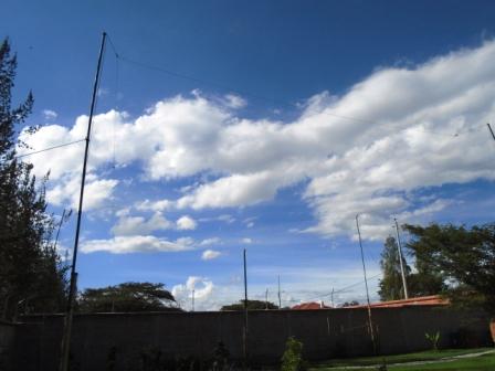
…in any case more time is needed and I will keep this loop up for further tests under different conditions.
February 20, 2015 Luis HC1PF