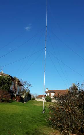
The new TX antenna (Vertical T) at IV3PRK
At the beginning of the year 2014 I dismantled my big shunt fed tower and moved to Ecuador. When I came back home in Italy, two years later, also its concrete basement was taken away to clear the garden and leave ham radio activity, but after a few months I decided to come back on Topband and began to install the antennas all over again.
|
|
|
IV3PRK - new Vertical T antenna |
|
|
|
Aluminium tubes |
|
|
|
|
Guying system |
|
|
Diameter/tichness mm. |
Outside diam. |
Inside diam. |
Section length |
Progr.heigth |
Polyester ropes by |
|
|
65 x 5 |
|
65 |
55 |
0,25 |
0,25 |
STI (DX Engineering ) |
|
60 mm. Isolator rod |
60 |
55 |
0,05 |
0,30 |
|
|
|
65 x 5 |
|
65 |
55 |
5,75 |
6,05 |
|
|
|
55 x 5 |
|
55 |
45 |
3,70 |
9,75 |
4 x 8 mm. ropes |
|
|
45+50+55 |
renforced |
45 |
42 |
0,65 |
10,40 |
|
|
|
40 x 2 |
|
40 |
36 |
2,70 |
13,10 |
4 x 8 mm. ropes |
|
35 x 2 |
|
35 |
31 |
2,70 |
15,80 |
|
|
|
30 x 2 |
|
30 |
26 |
1,65 |
17,45 |
4 x 5 mm. ropes |
|
25 x 1,5 |
|
25 |
22 |
1,25 |
18,70 |
|
|
|
22 x 1,5 |
|
22 |
19 |
1,80 |
20,50 |
two top loading wires |
|
|
Total vertical ant. Length |
20,20 |
|
sloping 19 m. long |
Structurally the antenna is the same I had in Ecuador, but changed from “Inverted L” to “Vertical T” in order to improve low angle radiation as preferable at high latitude locations. See inverted-l-vs.-vertical-t.htm page in the “HC1PF experiences” column.
The top wires are 19 m. long, sloping from 20.5 to 8.7 m. height (1 mm. diam.)
Despite the success of the K2AV FCP system in the HC1PF setup, I changed to the classic on ground radials, as I have here the necessary space.
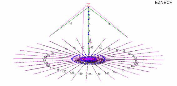
This is the Eznec “View Antenna” image:
and this is the elevation plot.
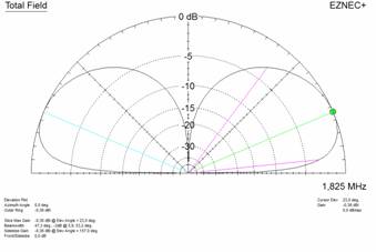 The source data indicates:
Impedance 20,72 – J 1,872 ohms.
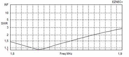
The L-Network calculated with TLW program shows:
C – parallel input: 2064 pF
L – series coil: 2,30 µH
The following is an SWR run after the insertion of this L-Network
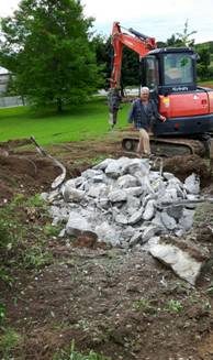
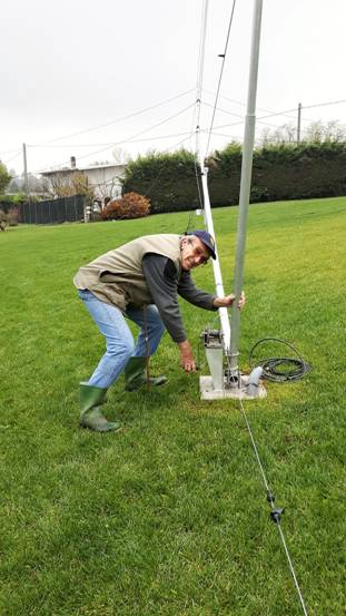
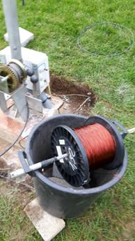
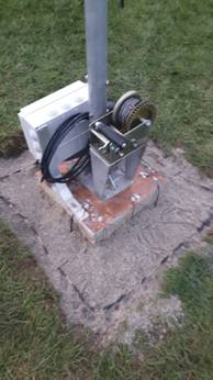
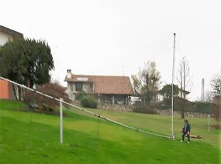 Rising the antenna was quite easy by means of a gear wrench and a gin pole: just me and my wife Luisa
The radial system
After reading the great QEX articles on this subject by Rudy Severns, N6LF, I learnt that there is no reason to exceed with the number and the length of radials: very small improvements going above the number of 32, and even worse by making them too long. In a direct correspondence with the author of EZNEC, Roy Lewallen, W7EL himself wrote me:
“Luis,
You can see by the current distribution on the radial wires that they are electrically longer than a quarter wavelength. At a quarter wavelength, the current should just reach maximum at the junction. I think you'll
find the best efficiency to occur when the radials are an electrical quarter wavelength or shorter, and increasingly poor as they get longer than a quarter electrical wavelength.
The electrical lengthening of the radials is due to the low propagation constant of the ground. The amount of lengthening (the effective velocity factor) that happens depends strongly on the height above ground as well as the ground characteristics. Calculation of the physical length needed isn't simple -- I recommend just shortening them until the current maximum occurs at the junction.
73, Roy, W7EL”
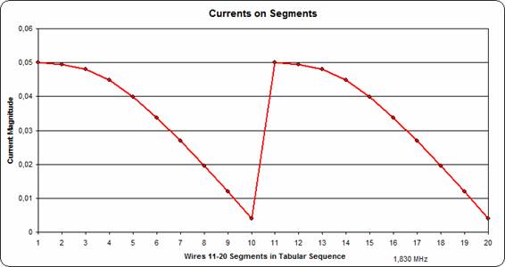
EZNEC reports all the detailed currents on the wires in a tabular form; it is much easier to see their whole development in the graphics of AutoEZ. This is the current on the first two radials of 40 meters length.
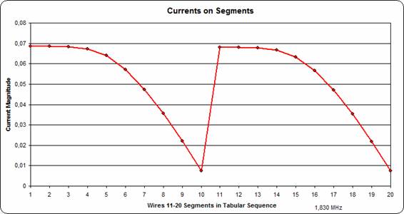
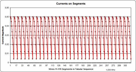
It is too much on the first segments and this causes a non-uniform distribution in the whole ground system as shown in the following graph, which includes all the 32 radials.

I found that the best length which accommodates a full quarter wave sinusoidal current is around 28 meters as shown in the following graphs.
This radial system with 32 radials, 28 meters long, shows a perfect uniform current distribution around 360 degrees: no reason to waste more wire!
Actually I made some measurements with the same dipole 76 meters long I was using in Ecuador for my BOG studies. There, on a poor desert soil, it resonated around 1.200 KHz, while over my garden grass in Italy it resonates around 800 KHz: thus quite a difference in the velocity factor. Then I tested the dipole on different heights and it is clear that lowering a wire to ground level its resonance changes a lot.
|
Dipole heigth |
Resonance Freq. |
Velocity Factor |
|
cm. |
KHz |
VF |
|
180 |
1810 |
0,92 |
|
90 |
1750 |
0,89 |
|
30 |
1640 |
0,83 |
|
15 |
1250 |
0,63 |
|
5 |
1070 |
0,54 |
|
0,5 |
780 |
0,4 |
My practical installation
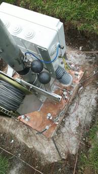
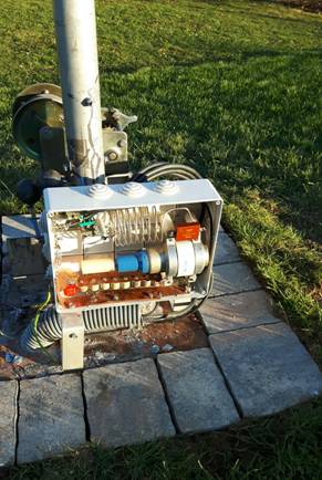
I covered the concrete base of the vertical with a copper sheet for easy soldering.
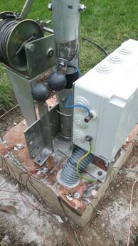
For lightning protection 1.80 m. long copper rods have been hammered down at the four angles and connected through a solid bus wire. For lightning discharge I used two iron 50 mm. balls as shown in the pictures. As static drain I put in the matching box a series-parallel combination of several 10 Mohm resistors.
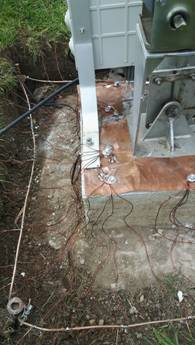
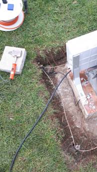
For radials I used enameled wire 1.32 mm. diameter (12 Kg.) and to be double safe with their connections, I soldered them first on the bus wire, and then on the copper sheet after tightening there with bolts. I wrapped with electrical tape the tinned joints before covering them with sand.
Impedance measurement made with AEA antenna analyzer
BEFORE installing the radials was: R = 27 Ohms - X = 13 Ohms - Z = 30 Ohms
Resonance point at 1.830 KHz with the top loading wires 20 meters long.
AFTER completing the installation of 32 radials, these were the readings:
R = 12.5 Ohms - X = 0 - Z = 12.5 Ohms, with resonance point still on 1.830 KHz.
Wow, almost 15 Ohms of ground resistance removed!
With these real impedance data, the TLW program indicates that the L-Network requires an input parallel capacitance of 3.000 pF and a series inductance of 1.9 µH.
Thus I just added a further 780 pF mica capacitor in parallel to the vacuum one.
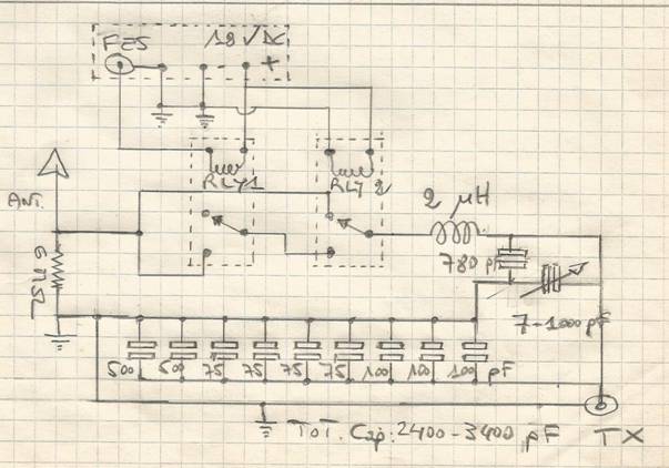
In the matching box are included also two relays for the vertical detuning while listening on a separate receiving antenna; Rly1 is a vacuum Kilovac HC1 for high speed switching.
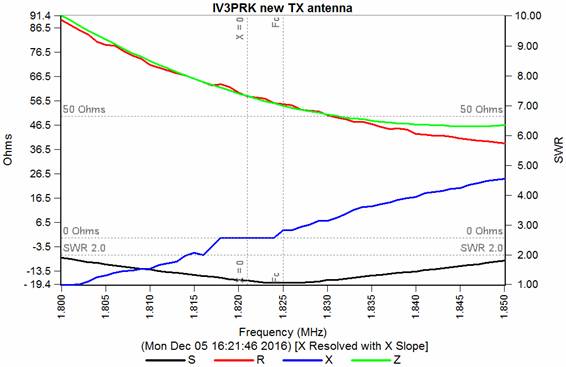
With the antenna analyser the 50 Ohms impedance was soon found, but the resonance frequency was gone down on 1.800 KHz. That’s probably due to the excessive inductance of the coil, but it was easier for me to shorten the top loading wires from 20 to 19 meters (as designed) and the results are given on the graph below.
Finally I made my wife happy when she saw all the wires disappeared in the lawn by means of 300 Gardenmate steel pickets bought on Amazon.

December 12, 2016 Luis IV3PRK