Trying again the Waller Flag at IV3PRK – part 1
Searching for the best design
The new WF will be built on a
8 m. long aluminum (50 mm.) boom at 13 m. height, attached to a fiberglass mast on top of an insulated 12 m. small tower.
Vertical wires are supported by 3 m. long fiberglass tubes (the first three sections of cheap 5 m. fishing rods - diameter from 29 to 16 mm.). Not yet decided the wire type: #13 gauge “Silky” wire by “The Wireman”, or normal #14 house wire …
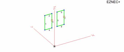
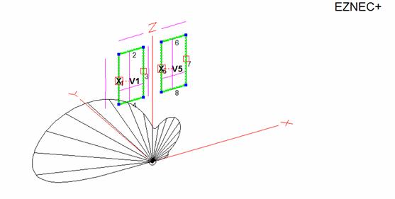
This is the Eznec design: wires 1, 3, 5 ,7 = 6.00 meters; wires 2, 4, 6, 8 = 2.90 meters
Varying the loads with AutoEz
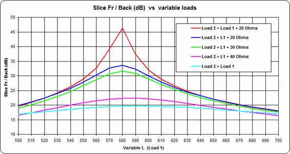
Load 1 is on wire 3 and load 2 is on wire 7.
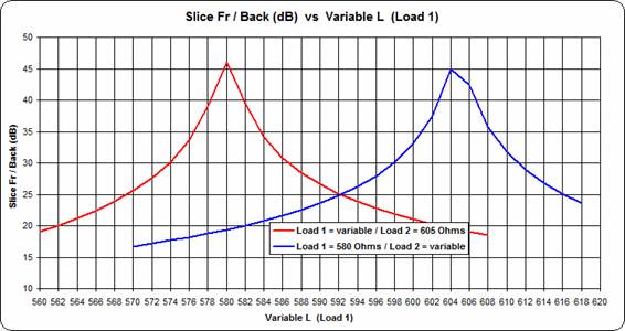
The best F/B results at load 1 = 580 and load 2 = 605 Ohms, with an impressive 45 dB peak at 22 degrees’ elevation.
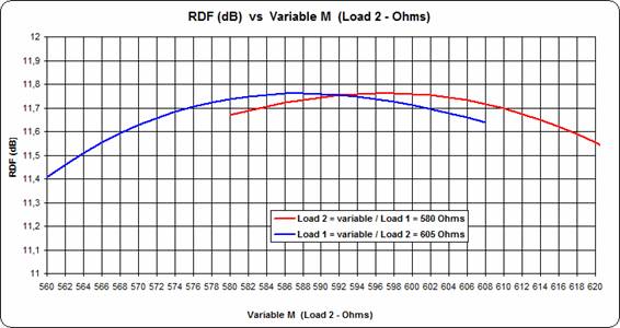
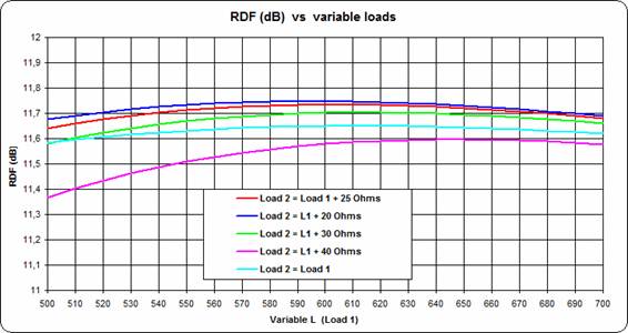
The RDF variation is less pronounced, but confirms to be better in the same region.
Transformers and feed system
 In the “Insr.Objects” sheet of AutoEz we substitute the sources on wires 1 and 5 with the transformers, and the phasing lines from there to a central feed point (source).
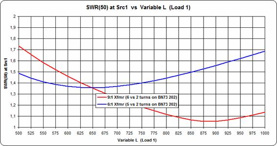
Being the loads in the 600 Ohms area, it is better to use a 6:1 rather than a 9:1 transformer. The SWR now is well below 1.5:1 as recommended by N4IS.
Phasing lines length
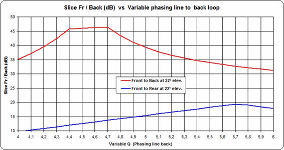
Now, with dimensions and loads fixed, let’s see what happens by varying the phasing lines lengths. Line 1 (to the front loop) is kept fixed at 5.00 m, while line 2 (to the back loop) is varied from 4.00 to 6.00 meters.
Phasing lines are 100 ohms impedance, made by paralleling two RG58 cables.
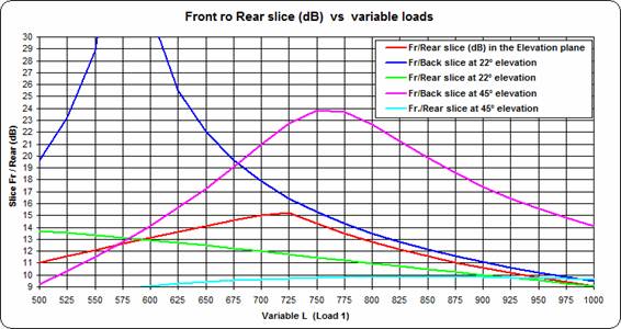
Here it is not easy to take a decision. If we look at the Front to Back graph (red line) we see the best results (F/B of 45 dB) occurring with the phasing line to the back loop shorter than that to the front loop. But if it is more important the Front to Rear ratio (blue line), our phasing line to the back loop should be longer (5.7 m.) than the front one.
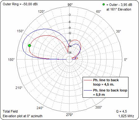
But if we examine the elevation lobe, we see that the blue one is better, with a lower high angle radiation
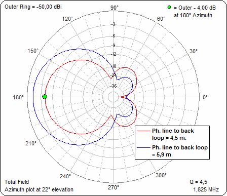
Also in the azimuth plot we see that the blue lobe is much better.
The highest 45 dB null of the red pattern is very sharp, only at 0°, without any practical effect.
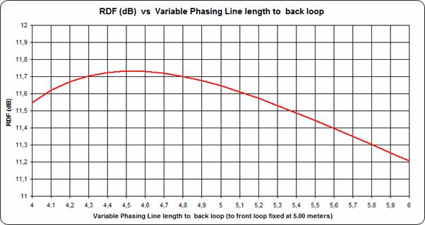
The Benchmark for receiving antennas is RDF and, according to it, - see the graph below - the line to the back loop should be half meter shorter than that to the front one. (4,50 meters to the back vs. 5.00 meters to the front)
Loop dimensions
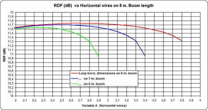
This graph shows the RDF by varying the horizontal wires length on three different boom lengths. The curves are pretty flat, not critical at all.
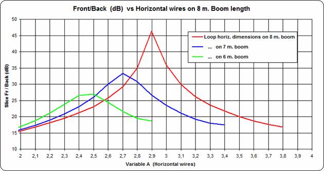
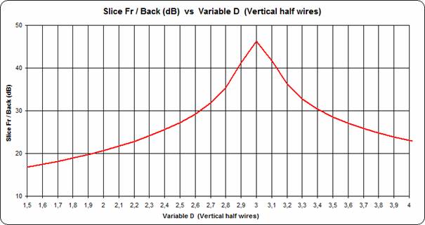
Quite different is the same graph showing the F/B at elevation angle of 22 degrees. There is a sharp peak for the loops 2.9 wide with 2.2 m. separation on 8 m. boom (or 2.7 with 1.6 m. sep. on 7 meters boom)
Of course the gain increases with loop dimensions:

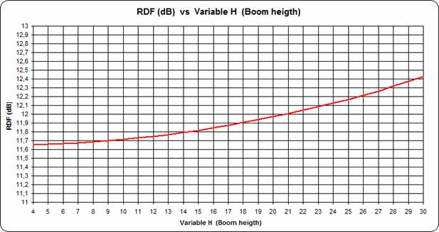
As usual, the higher the better!
Also for vertical wires variation, no much difference in the RDF
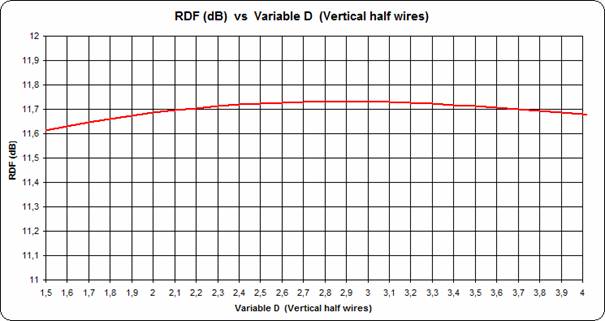
While (for 2.9 m. wide) the best vertical dimension is 6 meters (3 + 3 vert. wires)
Last check of the loads value
So, for the following definite Waller Flag design, let’s check again for the best loads:
Boom 8 m. – 12 m. high – Vertical wires 2 x 3.00 m. – Horizontal Wires 2,9 - phasing lines 5 meters to front and 4,60 to back loop
But, again, is Front to Back at DX elevation angle the most important parameter, or F/B at continental elevation angle to limit background EU QRM?, or is better to take the Front to Rear parameter mostly into consideration ? Everyone has is personal choice.
The RDF graph indicates that the loads should be in the 575 – 600 Ohms with definitely 25 Ohms of difference between each other.

For this last definitive antenna design let’s check again the transformers windings.
With 600 Ohms loads it seems better to use 6:1 xfmr ratio: just reduce one turn on the primary winding.
Luis IV3PRK September 17, 2016